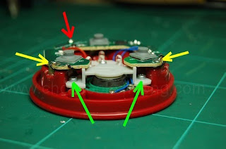
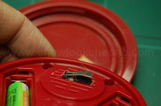
Lets take the toy apart gain. The reason we need to do this is to prepare the hole for the micro-switch, which is inside the speaker's echo chamber. And the speaker is held by a plastic clamp which is secured by two metal screws (green). In order to do this, we need to move the circuit board out of the way for a while. So, remove the metal retaining screw (red) first.
Quickly take the soldering iron and desoldering pump to remove as much solder as you can. But do this (melt and desolder) within 3 seconds per attempt as it is very reasy to destroy the tracks. You need to remove as much solder as you can so that its easier to detach the board from the battery tag. Becareful about the wires soldered to the tags.
You do not need to remove the solder completely as the next step is to melt the solder again and gently lift the board. Melting the area not only disconnects you from the battery tag but also the hot melt glue hidden inside. Repeat this for the other side. Do not let the iron heat the tags for too long as they are made of metal and the heat could melt the plastic holding it.
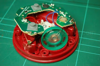
With the board out of the way, you can now unscrew the clamp and move the speaker out too. Just to be safe, use a low tack tape to stop the loose PCB and speaker moving about. This would not only keep the speaker from ratlling and wearing the cables down but also to keeps them from snapping off. A soldered joint is hardens the cables and breaks easily when force is applied.
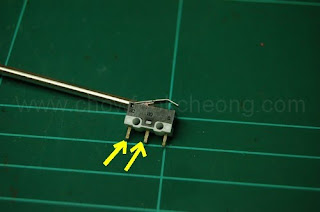
Now, prepare the micro-switch. For this model, the two yellow arrows means these are the legs that will complete the circuit when the metal lever is pressed. Here, I tested the switch by bending the metal a bit.
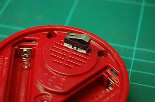
Turn the toy upside down and mark a rough rectangle for where the micro-switch is to be positioned. Don't worry as although the plastic feels hard, it is actually very soft and is easy to work with.
Before you use the hot melt glue to the micro-switch, you must solder the wires to the legs (marked yellow form the picture above.). Then bend the legs to conserve space.
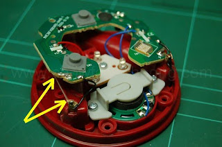
Look carefully where the two yellow arrows are pointing as you need to make a small deep rectangular hole for the wires to come out of the speaker's echo chamber.
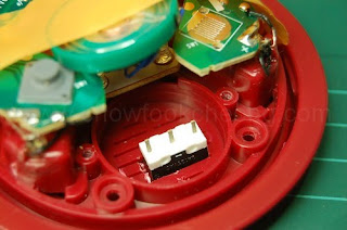
As the hot melt glue cools down, make sure the micro-switch is positioned like so. You do not want it to be jutting more than 0.5mm or so. You must test fit again and again before using the glue. One way to know is to lie the toy on a flat surface. If you hear the micro-switch 'clicks', its jutting out too much. Remember the position and as the glue cools, quickly do the test fit again and again. This is the point of no return and oh, the glue also clogs up the speaker grilles. And becareful as hot melt glue can burn figers.
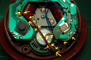
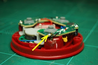
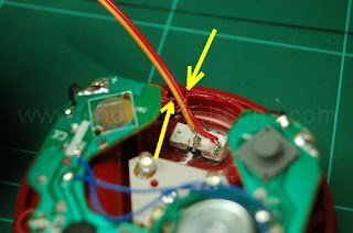
Gently push the speaker back into the echo chamber. As expected, it wil not enter fully due to the micro-switch underneath. Do not worry if you cannot secure it with the plastic clamp as the fitting is quite tight. Screw the board back to the toy. Then solder the board back to the battery tags, ans as you melt the solder, push the PCB down as much as possible but not too hard. Now, solder the two wires as shown by the arrows. Be patient because there are other wires and they WILL come off when the solder melts.

For the back cap, look for a piece of scrap plastic or anything that has about 1mm thickness. Tape it exactly to the area where the micro-switch will swing round.

And if your micro-switch does not work, gently bend the metal tab. This takes a lot of patience to make it work and the plastic holding the tab can easily be broken if you're not careful.
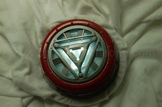
Once everything is done, attach it to a shirt. If you press the top cover, it will work normally. But you will notice the sound has become 'quieter' since the hot melt glue and switch has affected the speaker's membrane and the grille. This is the side effect of the mod.
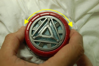
To have the lights come on without activating the sound or having to tap the front cover, just twist it and it will turn on or off. So, try to position the cap in such a way that one triangle position turns it on. So, thats it for the modification.