I accepted this job because my Daughter was excited about Iron Man coming to her house
After I have shown the Arc Reactor to Richard, I was given an Iron Man armour to work on. This is because they need to show how the toys work during roadshows. This means, I cannot apply any modifications to the Arc Reactor except to bypass the circuit to light the YELLOW LEDs permanently.
I accepted this job because my Daughter was excited about Iron Man coming to her house |
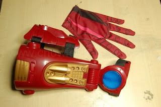
The armour has been in a few shows and its wear and tear was starting to show. So, before I start on the modifications, I need to repair the armour to make it last longer before the next show and so on.
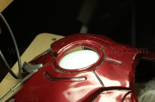
As you can see, a lot of people were curious about the 'headlamp' on the armour and so, I was told, they keep pressing it, which lead to the mountings behind it failed. As the result, there is a nice big gap for me to work the wirings on.
|
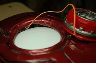
Ah, the magic of illusion. Behind the armour, you can see the arc reator. I was told its some sort of a torch lamp. After a premilinary look, I now know which area to work on, which is at the 'V' shape of the neck since that area is flat.
|
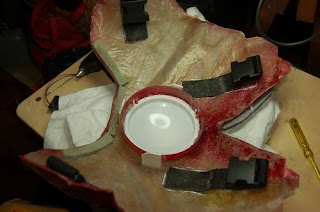
I am surprised at the amount of dust in the armour. Anyway, the 'neck' area needs to be reinforced.
|
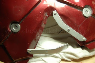
Then the mountings for the 'Arc Reactor'. Surpirsingly, hot melt glues are very handy at this point.
|
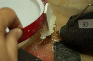
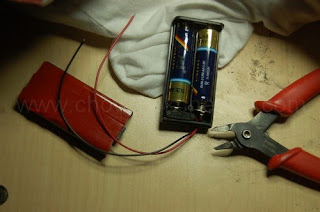
Just like the toy, I am keeping the voltage to 3.0 volts, but this time, I am using a battery holder for 2x AA batteries instead. It also has a switch. Here, I double-sided the cover. The design of the holder made it hard to keep the cover on if you do not close it properly. |
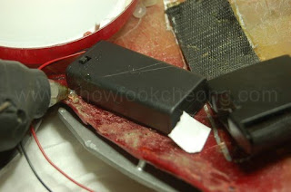
After cleaning the surface, I placed it on the armour and just to be safe, I hot melt glue it as well. I hung the battery holder 'upside down' too so that they can reach the switch from the neck. And also because I am hoping gravity will keep the whole piece on. |
Because the request is to only modify the Arc Reactor Toy to switch the LEDs permanently on in the armour, the modification is not that difficult. The only difference is that I cannot use a micro-switch as the armour cannot utilise the back cover. So, I have to think of another method. This time, I am going to use cables and at the same time, fit an external power source since taking the toy out and sticking it again will wear the double-sided tapes as they need to reaplly it again and again. So, I will now modify the toy to Even Stage and then take it a step further to include the cables.
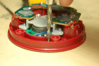
Open up the toy and locate the two screw pillars which are very close to each other. This is the top of the toy. Use a 3mm drill bit and make a small hole as shown.
|
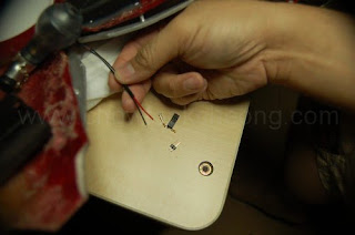
Once you have done that, leave about four inches of extra cable in this end. Tie a knot to secure it in case someone pulls the cable accidentally. The knot must be small so it can fit into the crevice.
|
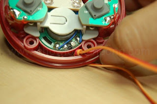
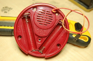
You can see on the other side where the cable comes out. It is not obstructing anything. Although I have tied a knot here, later on, I found out it is not necessary. Note the connection of the battery terminals. The bottom 'V' shaped metal is just to continue the circuit from one battery's positive end to the next battery's negative end.
|
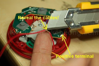
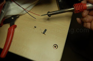
Decide which cable colour to connecto to which battery terminal. Here, I use Red to represent 'positive'. Measure the cable distance and where it comes out of the 3mm hole and reaching the positive terminal on the right, cut the protective sheath away to reveal the wire. Solder this wire to that terminal.
|
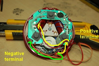
Continue wit the red cable until you reach where the original wires to the LEDs are. Solder it to the RED wire and not the BLACK wire. Then use the other cable and solder it directly to the negative battery terminal as shown with the green arrow.
|
Remember, with this modification, it is not adviseable to put the two AAA batteries into the toy. So, you have to use the external batteries. Here, I am testing the circuit before I coninue with the next stage.
|
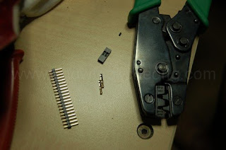
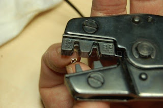
As the wires I use are very flexible and yet gragile, I cannot use those heavy-duty connectors. Rather, I am using the PC header connectors. So, you will need a PC header crimp tool for this. The picture above shows what are the items needed. If you do not have a crimp tool, you can use other connectors instead.
|
Let's prepare the battery cables first. Strip about 3mm off the sheath to reveal the cables and tin it. Tinning is where you apply solder to the wires so that it is easier to solder to tags, connectors or other wires later. But do not apply too much solder or heat it too long as the plastic sheath can melt easily.
|
Next, slip in a few inches of heatshrink tube into the wires. I do not want to use electrical tape here as it looks messy and their glue can fail after a very short time.They're good for when you're mending cables or search for faults, though.
|
Quickly melt the heatshrink. I can use a soldering iron and 'brush' on it but it won't look nice. So, I use a flame torch. Thanks to me, I nearly burn my T-Shirt but because this is not the shirt I used for YouTube, its not screen-used (Ha ha ha)
|
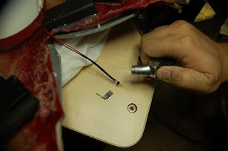
With the osldering done, I now use the crimp on the red/white cable which is attached to the toy.
|
Even with the mountings repaired, the gap is still there. And so, this is where I use it to hide the cables.
|
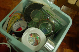
I am now learning to appreciate the different types of tapes for this hobby. They are fast and easy to apply in places where expoxies are not allowed.
|
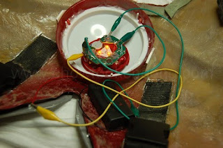
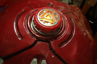
There. Switch it on and it works. The LEDs are very dim, even with the nearly fresh AA batteries. Since I cannot even put tracing paper on it, I heave to leave it as it is.
|

And so, the toy is done and the show goes on. Still, if it was up to me, I would have removed the 'lamp' behind and firred my Advanced Stage version on it. Richard is pleased and I get to sleep soundly. But before he left......
Heh. Heh. Heh. Thoughts are stirring in my head......
Should I modify it or not?