THE WAITING GAME
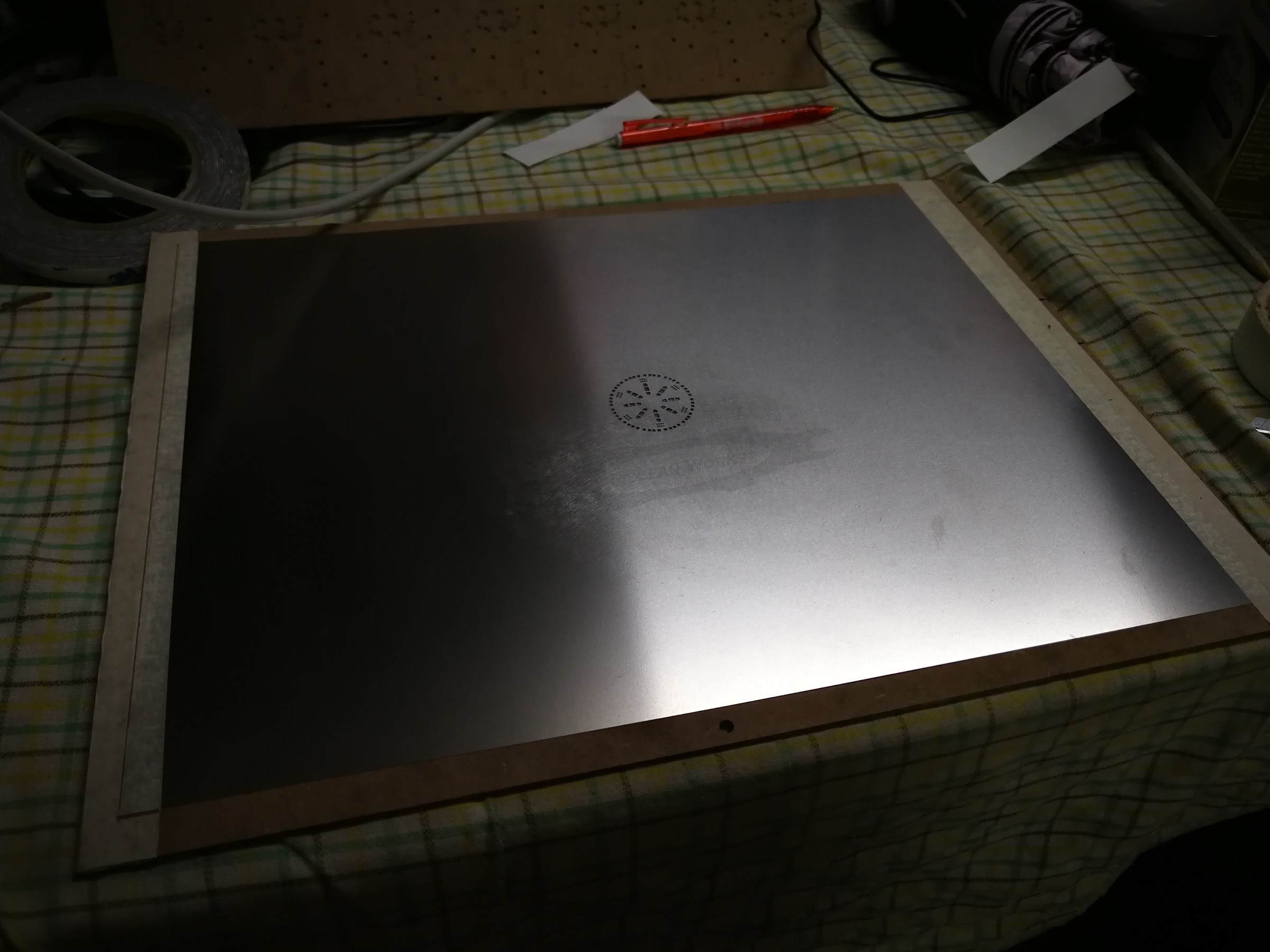
I’ve been needing to do this since the stencil came two months ago. As the stencil is huge (280mm x 380mm), it is quite impossible to clear a flat space on my Works Table for it to lie on. And so, I had to wait until the other table is ‘free’. I did want to reduce the size of the stencil but without the proper tools to make clean cuts, I risk destroying the metal sheet.
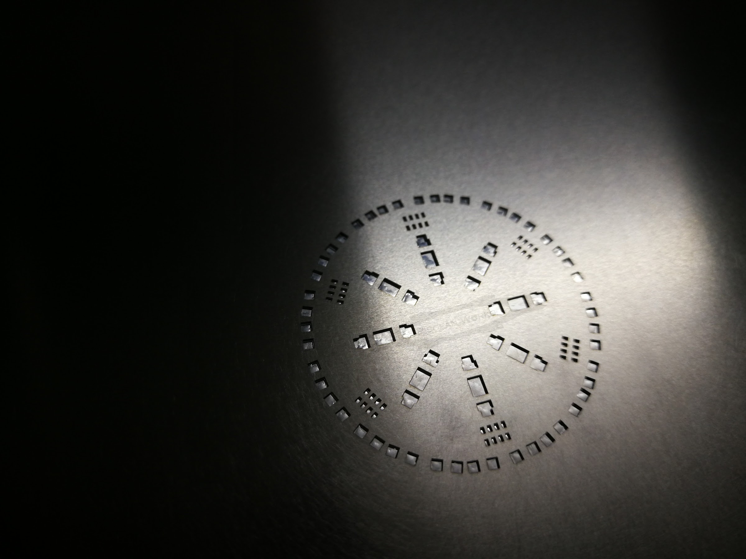
For tonight, the main aim is to position the 1.1mm thick PCB template as accurately as possible, where all its opening matches the solder areas of the PCB. It took me a few tries but eventually, it is 99% complete.
HOW THICK IS IT?
I think the standard Stencils from JLCPCB is 0.13mm. And in their FAQ, they have various thickness from 0.1mm to 0.12mm to 0.15mm to 0.18mm and 0.2mm. Anything outside these will be extra.

WHY ALL THE EFFORT?
The design of the Razor Crest engines uses a lot of LEDs. There are about 32 SMD LEDs and 6 network resistors which translates to about 112 soldering points. I calculated that if I were to hand-solder, it would have taken me hours. Although I am using a pencil pointed soldering bit, it is still quite chunky when it comes to soldering these smallest SMD components. For every soldering point, I have to test the circuit again and again.
One of the solution to speed up the manufacturing process, is to outsource them. For a few boards, it would be OK but if I were to go on a small manufacturing run, that could take a good chunk out of my budget. The only solution I could think of would be reflow soldering. So, I am going to use this design to test out my theory before I decide to do it on a larger scale. Even if this process takes me 45 minutes from applying the solder paste to populating the PCB to reflow them, it is still quicker than hand soldering which takes hours.
