The Stormfang is is an exclusive gunship reserved for the Space Wolves. In this Universe, it is the definition of aerial superiority.
Around this time in the 2015’s, Warhammer model designs have evolved into the concept of creating a core product and then gives optional parts to turn the model into different variants. This is not a new idea and it has been practised by various manufacturers since decades ago. This Stormfang can become, the Stormwolf.
In other words, you can turn a flying freezer cannon into a flying container. I am going to document how I created the lighting for this model, by using the first copy, courtesy of Mr. Edward Dr. Gunpla, before I could scrape enough cash to get one as I as out of a Job.
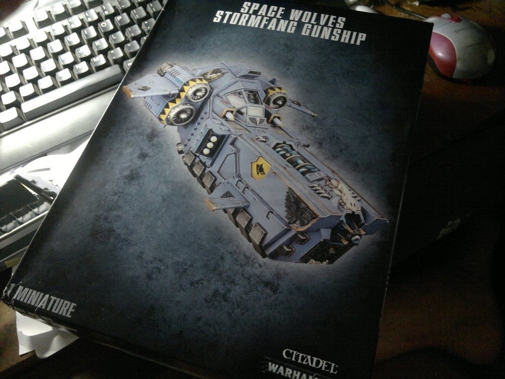
This is Edward DrGunpla’s Storm Fang which he is loaning to me for a few weeks. Yes, I am going to take a look at it for its lighting potential.
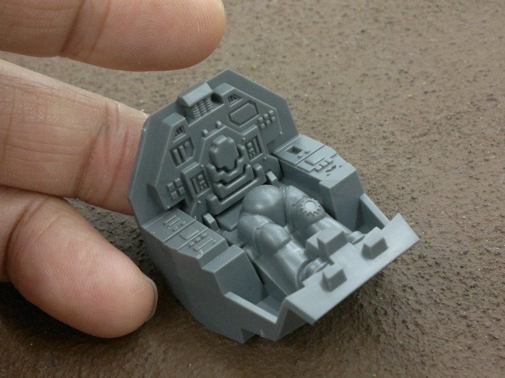
The pilot’s cockpit is quite similar to that of the Stormtalon and the Ravenwing’s Dark Talon except that the Stormfang version has the pilot’s lower torso molded in. But this is not important unless you really need to change pilots.
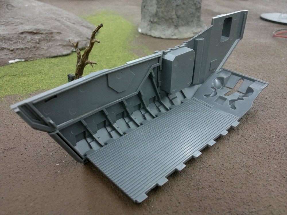
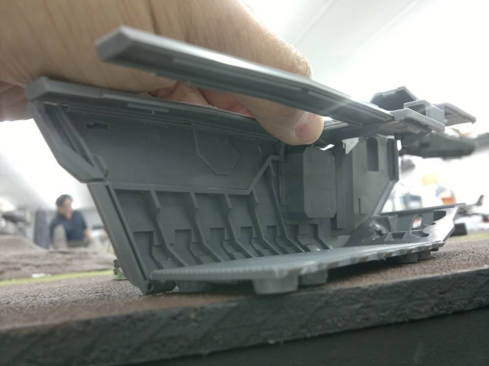
Here is the exciting part, the troop area. This is the partially dry-fitted Stormfang. I shall call this the Stormfang from now on as this is what Edward DrGunpla’s build will be. Call it whatever you will on what the shape is, but to me, this is an awesome 16-man troop transporter with a battering ram!
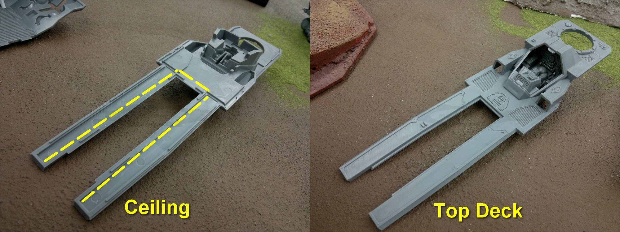
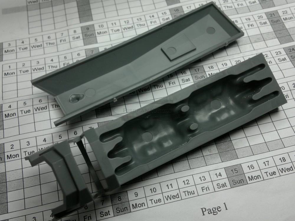
Looking at the single ceiling/top deck part, my first idea which was to light up the ceiling with SMD LEDs is now maybe not possible. I have to create a circuit board or ceiling which needs to be fit into both Stormfang and Stormwolf variants. Therefore, this ‘U-shaped’ PCB would cost quite a fair bit.
So, I need to look at this from another angle and throw caution to the wind. If the user wants to leave the middle assembly open, then the initial idea would be great except that when its open, the lighting effect is totally lost.
Not only that, I have to deal with their front Helfrost Destructor, which, would be bad if it is not lit, right? I was hoping the model would come with a clear part too but alas, it was not to be.
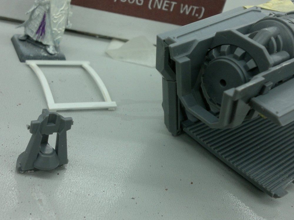
This is the front end of the Helfrost Destructor, Which, I suppose, you can drill in a 3mm LED. But in my mind, I am thinking something more if the front nozzle thingy can be omitted.
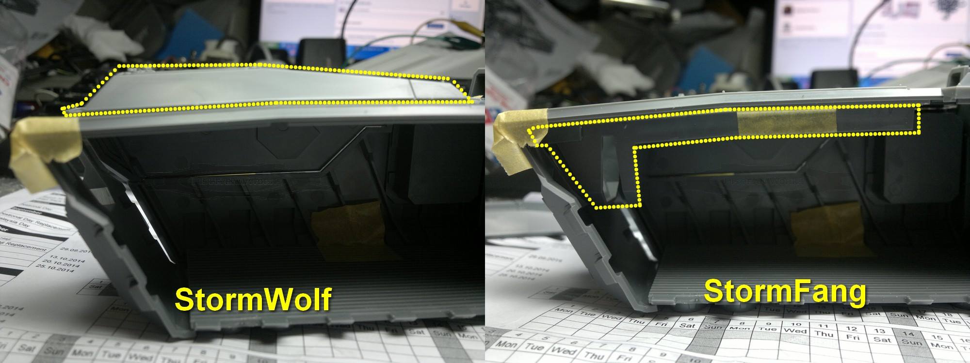
Coming back to the challenge I am facing, I need to design a board which can accommodate the two modes as each have different measurement and also, heights/depth in there. If you look a the two images above, the only thing that changes were middle parts. And so, the circuit board design would reflect that change.
And with these two parts, the design and dimensions of the board is confirmed. However, the PCB would need to be mounted using epoxy or other glue except CA aka Superglue.
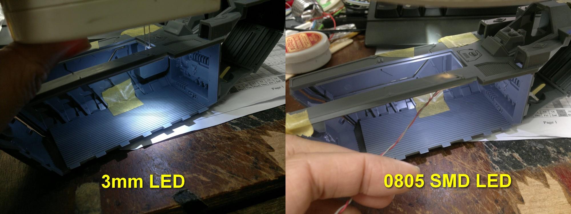
Here are the difference between a 3mm LED and a SMD version. Just like the AMT Tydirium Shuttle, the SMD LED’s light is all over the place. And unlike the Tydirium Shuttle, the area within the Stormfang is huge and so, the light is not that bright. I had to use the lamp to block out some of the room’s lights to show you this. The SMD LED gives a wide spread of light but is only effective within a small area.
The 3mm LED on the other hand, is bright and has a nice round hot-spot due to its clear resin lens. However, unlike the Imperial Guard Valkyrie, there are no ‘lampshades’ to reduce the diameter of the hotspot. So, for a 16-man area, putting a 16 LEDs or even 8 is not possible. The LEDs’s bright hotspots would overlap each other and cancels other LED’s hotspots, making the whole area look uniformly lit.
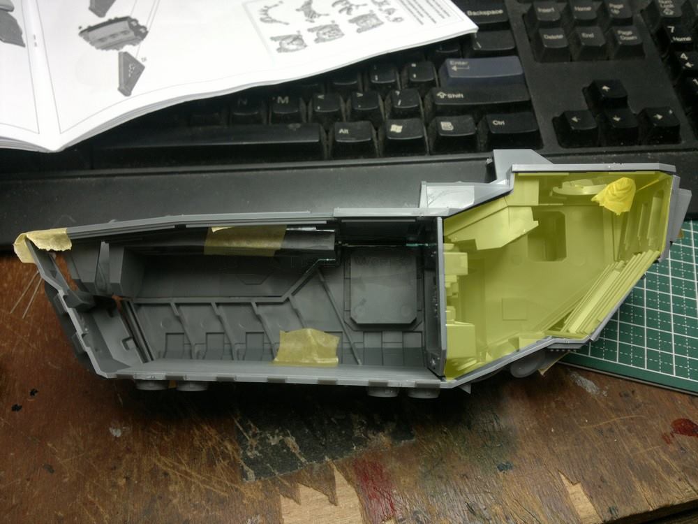
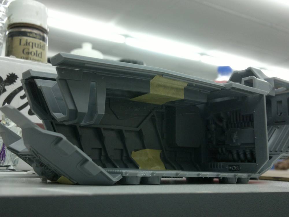
If you look at the rear of the model, the yellow area shows that there is a lot of unused space. I can stuff batteries in there and other circuit boards if they so wished. But if my electronics and or other figures at the front gets too heavy, I can put some counter weights in this area.
This is good news but it is not for me as I would still need to design a new circuit board where the ceiling lights are the main issue here. I do not even encourage the customer to solder a bank of LEDs for the ceiling lights.
And so, for this week, I will design the new circuit board for the Stormfang.
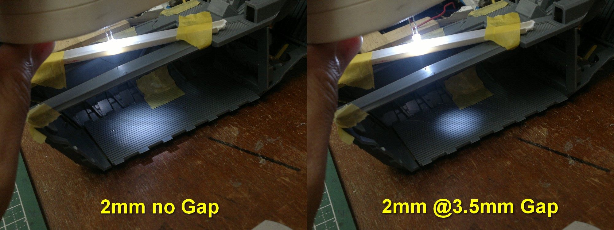
I have decided to use the 3mm LEDs because their hot-spots are very nice. One way to create a smaller hot-spot is to make a small hole with a suitable diameter for the 3mm LED. The image above shows the effect of the 3mm LED shining through a 2mm hole with two different distance.
The 3.5mm or so gap between the LED and the hole creates a wonderful effect but note the brightness of the LED has been compromised.
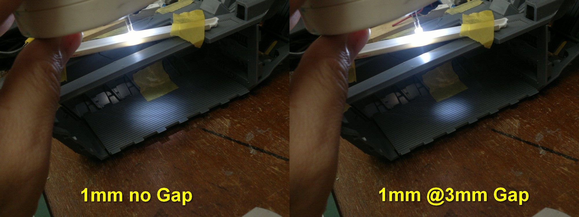
Now, let’s try with a smaller 1mm hole. The effect of it being lifted up by about 3mm created a tighter spot than the 2mm hole.
In the end, the effects are promising but bear in mind, the thickness of the plastic roof is about 1mm. I guess if I increased the board’s thickness to the standard 1.6mm for PCBs, the effect could be much better but I am not sure on this one. However you look at it, at most, there would be about 2 to 3 LEDs instead of the original eight I had planned. Creating more holes would be nice but their hot-spots would overlap each other very quickly, thus negating the effect of a dimly lit transporter.
Again, this time, the LEDs would be soldered using an unconventional method to achieve this effect and the two parts (Stormfang Helfrost Destructor and Stormwolf Air intake) allows for this.
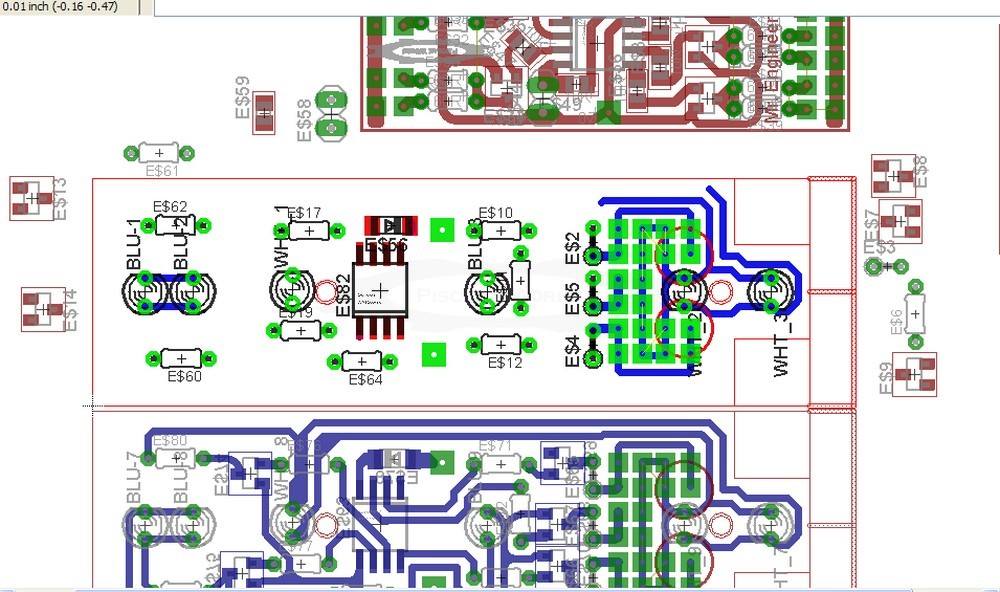
Well, this is a SNAFU for me. All the while, I was rushing to complete this board and still attend AniMangaKi 2014, I forgot to check and re-check my design. The board’s design needs to take advantage of a Stormwolf’s part (which has an unusual cavity) yet compact enough that it still fits snugly. Hence the mixture of normal electronic components and SMD (surface mount).
The problem started when in my haste to complete this design, I totally forgot about the SMD’s orientation when flipped over. At first, I thought its just the pin connections were flipped but when I looked closer, the power lines were wrong too. So, I scrubbed away the design and started again. Then I realised, ‘Hey, I don’t need so much LEDs for this!’
 I am designing this to be just a simple Troop Transporter or a Gun Ship with just the thrusters. Unlike the Stormtalon, I am not going to light up the vectored and lift thrusters underneath.
Imagine the crazy drilling and modifications for the wires to get through a single piece of flat plastic. No, Sir. I secretly hoped the floor of the model was made of two parts. Alas, it was not as its very expensive to produce. Because if you look at the ‘flooring’ part, instead of a long single piece, it could easily be made up of 10 parts; 2 for the floor (so that it is hollow and I can thread the wires through), and 8 for the thrusters.
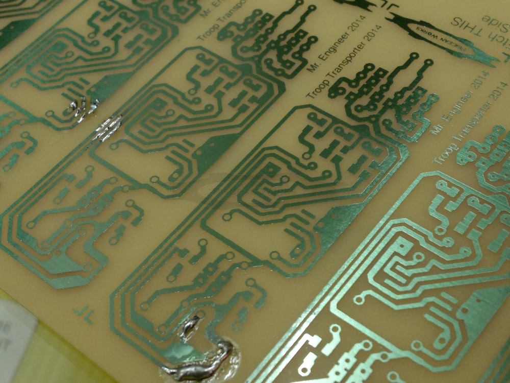
I finally got the Circuit board back today. Unfortunately, the guy who used to do them for me has resigned and the replacement who took over said he will NOT drill the holes for me and even offered to lent me his drill instead. The shop was experiencing some manpower issues. So, I got charged only for the etching of the designs. He was also hesitant to drill since the some of the pads I designed were too small and the tracks might come off.
As for the solder blobs on the board, I guessed they over etched some areas or, they accidentally touched the photo-resist coating during the pre-etching stage which came off. This is because the pattern did not look over etched.
This affects my prototype stage as I might need to buy a decent PCB drill with a stand, that is, to keep the 0.8mm drill bits from snapping off.
It’s been four months since this prototype saw any progress. My apologies to Edward DrGunpla. Time was not on my side as my new Job requires my full attention. At least, there is food on the table and my debts are slowly being cleared away.
I have finalised the programming for the thrusters and also the lighting effect for the Helfrost Destructor. Hopefully, this Saturday sees me complete populating the PCB but, its a fine time to run out of components.
Update 2022: There are light blue (the sellers called it Ice Blue) LEDs on the market since 2020 and that was the colour I was looking for. The blue LEDs I used (they were the only blue colour) were too intense.
For some strange reason, I could not upload Sunday’s picture despite trying for hours. But here’s a little bit more progress on the Stormfang although its going to be a year late.
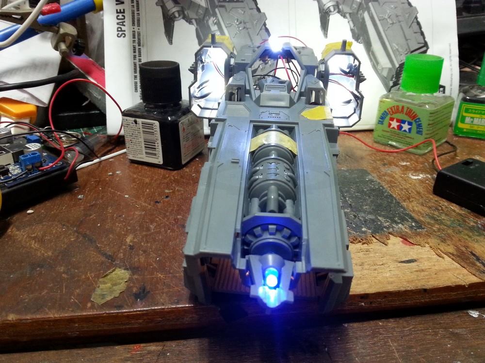
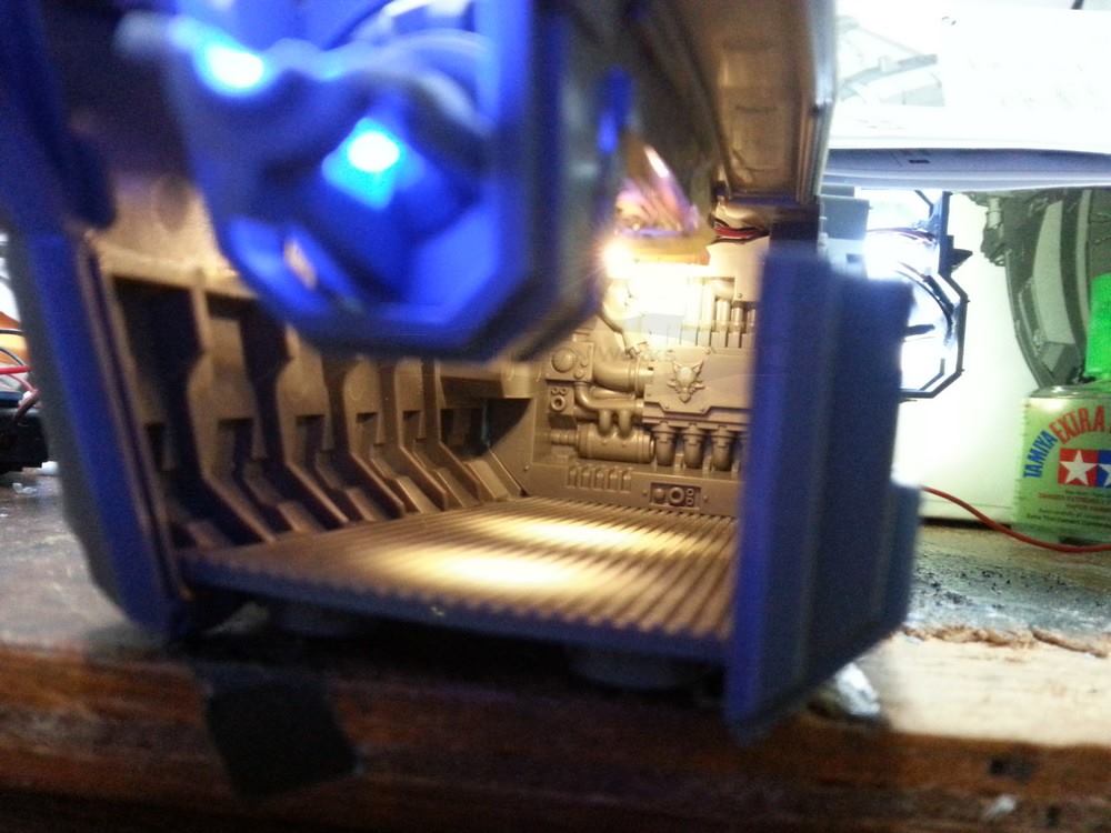
This is how the interior lighting for the Stormfang looks like; two semi-adjustable spots on the floor and one towards the wall, highlighting the Wolf. Because I designed the 3mm LEDs to be ‘adjustable’, there was not enough space for more LEDs. I am using the 3mm warm white LEDs for this as most of the spots I have seen are usually this colour. Plus, putting out a normal while light makes it look weird (to me). I have yet to adjust the floor spots, though.
The 4 Engines (bottom right) would be using the hot-spots effect from the 3mm white LEDs and they’re using the same flicker like the Stormtalon. And just as I was about to solder the 3mm Blue LEDs for the top Ice Cannon… they are no where to be found except the ones I bought way back, which was quite dim.
Finally, I had the chance to try out these blue LEDs. When I was at the shop, I was given two types of blue LEDs:
The first was a milky white lens (read: diffused) while the second is clear lens. The two lens actually does make a lot of difference as they produce different results.
Diffused (milky) lens:
Light is concentrated at the milky lens and so, the light radiated is very diffused and gives you a wide angle of light light a bulb. This is good if you want to illuminate a small area. But that area is very small.
Clear lens:
The clear lens concentrates the light. The light output is bright and has a very sharp hot-spot. Other than that, if you were to view this led on the side, the light is very dim. Its good for illuminating a narrow area from a distance.
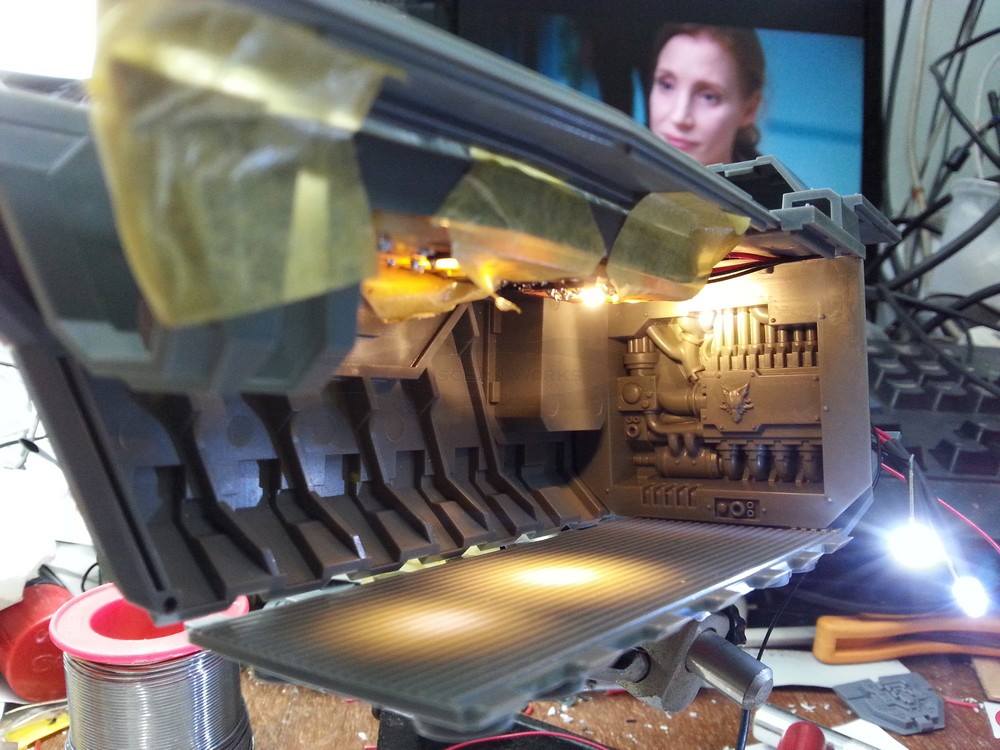
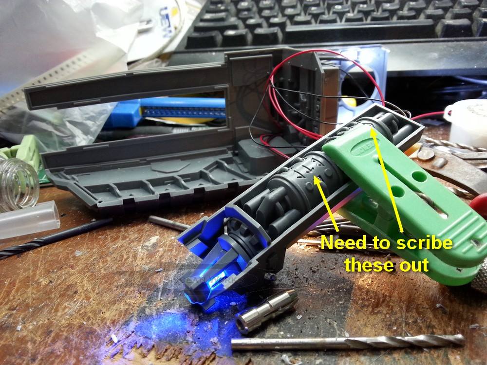
For the Stormfang, I used the diffused blue led to illuminate the Ice cannon and also the runes at the top of the barrel (of course, the customer will need to scribe out the runes for the light to shine through….
 )
)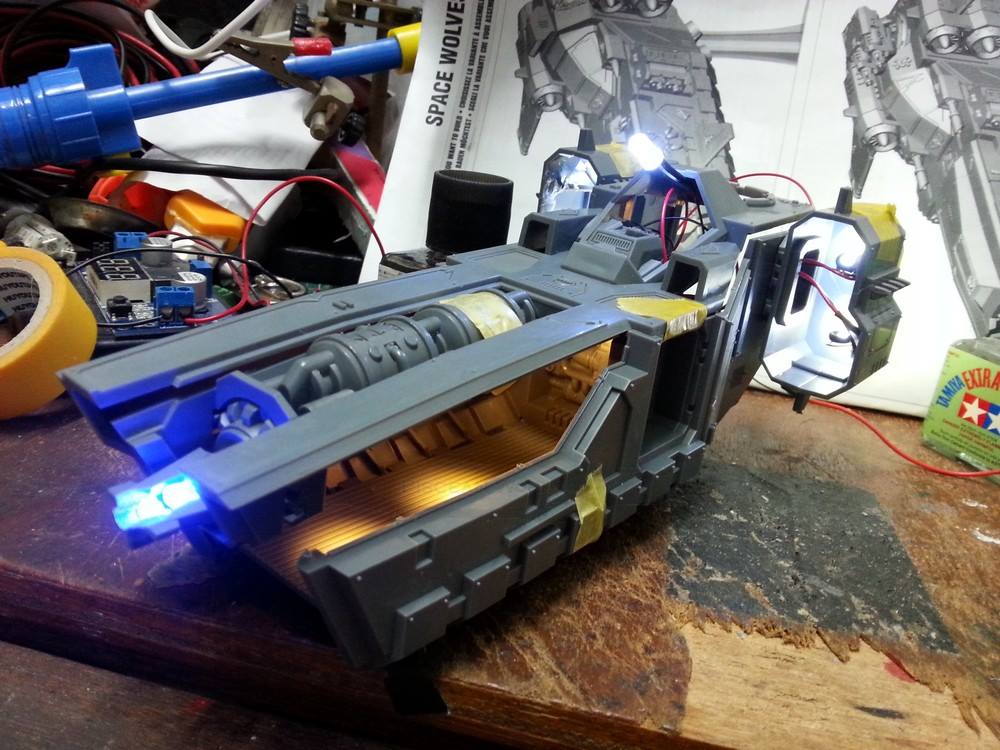
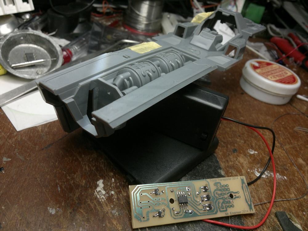
OK, finally, the lighting for the Client’s Space Wolves Stormfang is done! Do not be worried as to how it looked.
I designed and pre-wired the electronics into the Model. It is glued minimally so that Edward DrGunpla can still be able to access the insides and paint the model as he sees fit.
So, the features are:
1. Pulsing Blue LEDs for the Helfrost Cannon and also the topside barrels.
2. 4x Flickering LED thrusters ala Stormtalon
3. One white LED for the cockpit’s rear wall as the Client wants to light it up
4. 3x warm white Spotlights with two on the floor and one shining at the Wolf.
The Blue lights are not visible at the Helfrost’s topside barrels as Edward DrGunpla can do that himself eh, Edward?
The Warm white Spots are actually for the Stormwolf configuration where one can open the front ramp and see the interior.
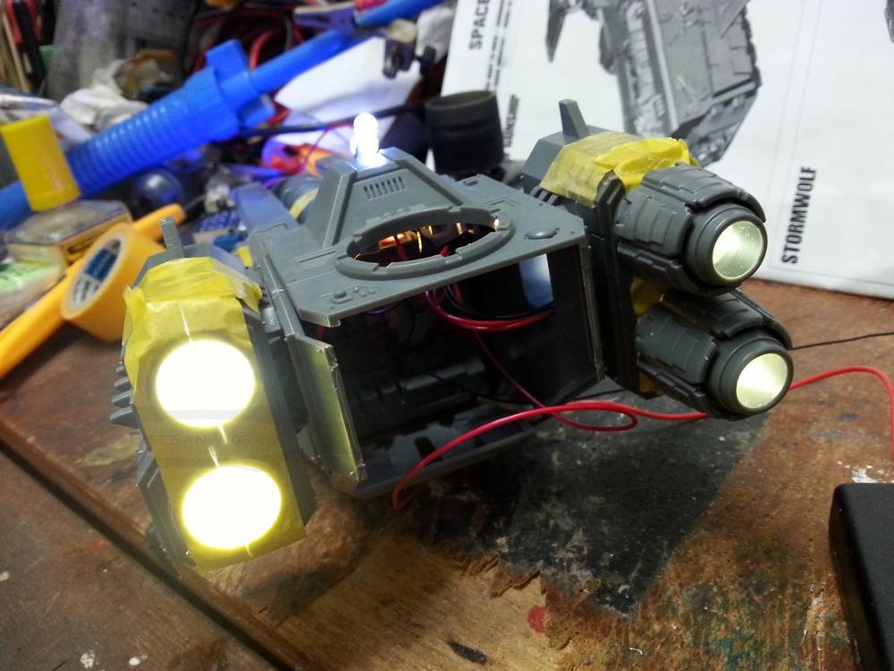
This is how the rear engine thrusters looks like. I put the yellow masking tape so that it would not shine into the camera lens. But it also has another purpose….
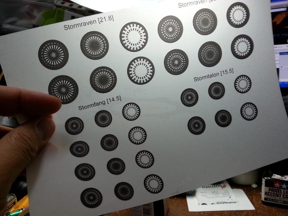
… which are for these engine designs. I have given the sheet for Edward DrGunpla to cut out the desired pattern and stick it inside the thrusters in place of the masking tape.
So, I call this done.
The Lighting System for this will not be available commercially as it is a challenge for those who does not have a Soldering Iron when it comes to mounting the LEDs inside the Helfrost Cannon.
