I got this Electronic Kit some time ago, way before the Pandemic started. At the core of the circuit is a 555 IC with the circuit configuration of a waveform generator. Everyone uses this versatile chip in a lot of applications and not just for electronic kits. Kits such as sirens, Electronic pianos, LED blinkers, timers, speed controllers, all have the chip in therm. By tweaking the resistors and capacitors, you are able to create the waveforms you need or, other solutions. Although the microcontroller is common, (ie Microchip Pics, Atmels, Arduinos, etc), the 555 timer chip is still very much relevant.
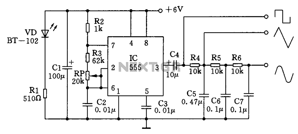
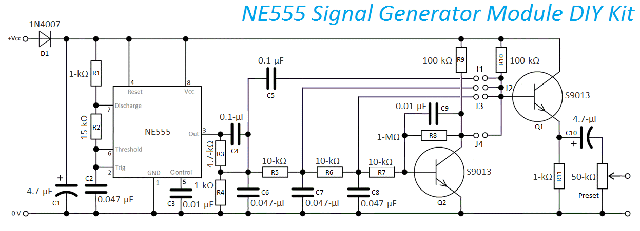
You can find a lot of these circuits on the Internet and here is an example of the one I took from. Basically, the circuit is able to generate three kinds of waveform from square, saw-tooth and sinusoidal. http://www.next.gr/oscillators/Multiple-waveform-generator-circuit-diagram-l59906.htmlYou can learn more about this kit from Peter Vis who explained a little more in detail. Basically, you can create your own waveform by inserting the jumper pin at the appropriate selection. The only thing you can change (without any modification) would be the amplitude. The link did suggest some modifications, namely a variable resistor for R2. Yeah, In most 555 circuits, you would have that and once you get the ‘ideal’ setting, you’d either leave it alone or, replace it with a fixed resistor. https://www.petervis.com/Electronics_Kits/555-signal-generator-kit/555-signal-generator-kit-circuit-diagram.html
OK, so, the IC and its socket bore the brunt of shipping but that can be easily remedied with a blade. For the 555 IC (right) make sure you re-bend the legs only once or max, thrice. I know I have one or two somewhere but I am too lazy to sweep through the debris, cobwebs or boxes to find them. I only have this evening.
I really, really hate 5-band resistors. Not only do they force me to manually calculate (OK, think) but because of the blue background, sometimes the red can be brown. Yes, I do have a multi-meter to sort it out but kinda dampens the mood a little. This is why I prefer the e24 resistors with beige background.
A far cry from what I was use to when I started with electronic kits in my pre-teens. The FR4 fibreglass PCB boards are so common now compared to the brittle FR2.
Like any other electronic kits, since these are through-hole components, you are going to insert the components (on the component side) and then flip the board over for soldering. It makes sense if you insert the lowest component first. In this case, it would be the resistors followed by the black diode.
When you flip it upside-down, and if the board is uneven (various components of differing heights), you will have soldering since some of the leads of these components would be exposed or not close to the board. And you will have to re-solder again, which is not fun because depending on your experience, you could end up de-laminating the board or burning the component with your soldering iron.
Net up would be the smaller brown capacitors followed by the bigger orange ones before me move on the there bigger electrolytic caps and eventually, the transistors. I know I should have soldered the 8-pin IC socket before the orange capacitors but hey, I know what I am doing…. not
Finally, the 555 time is inside the 8-pin socket and we can call it done. This is the easy part and I am usually not too concerned since most of the components are not polarity sensitive. But, I might want to RTFM incase I soldered the Transistors wrongly.
DID I GET IT RIGHT?
How would I know if it worked? I would either need a LED or a multimeter to test the pin #3 of the 555 IC. If the LED blinks or the meter’s needle moved, this means the chip is working. Next would be to connect the outputs to an analogue multi-meter and see the needle move. In theory, I can connect a LED at the circuit’s output to observe how its lights up under different waveforms. Ultimately, I would like to connect a passive buzzer to get that specific type of sound. But ultimately, an oscilloscope screen would be the most fun of all.
And then, why not select all the waveforms at once?
But this will have to be for another time as my evening’s up.