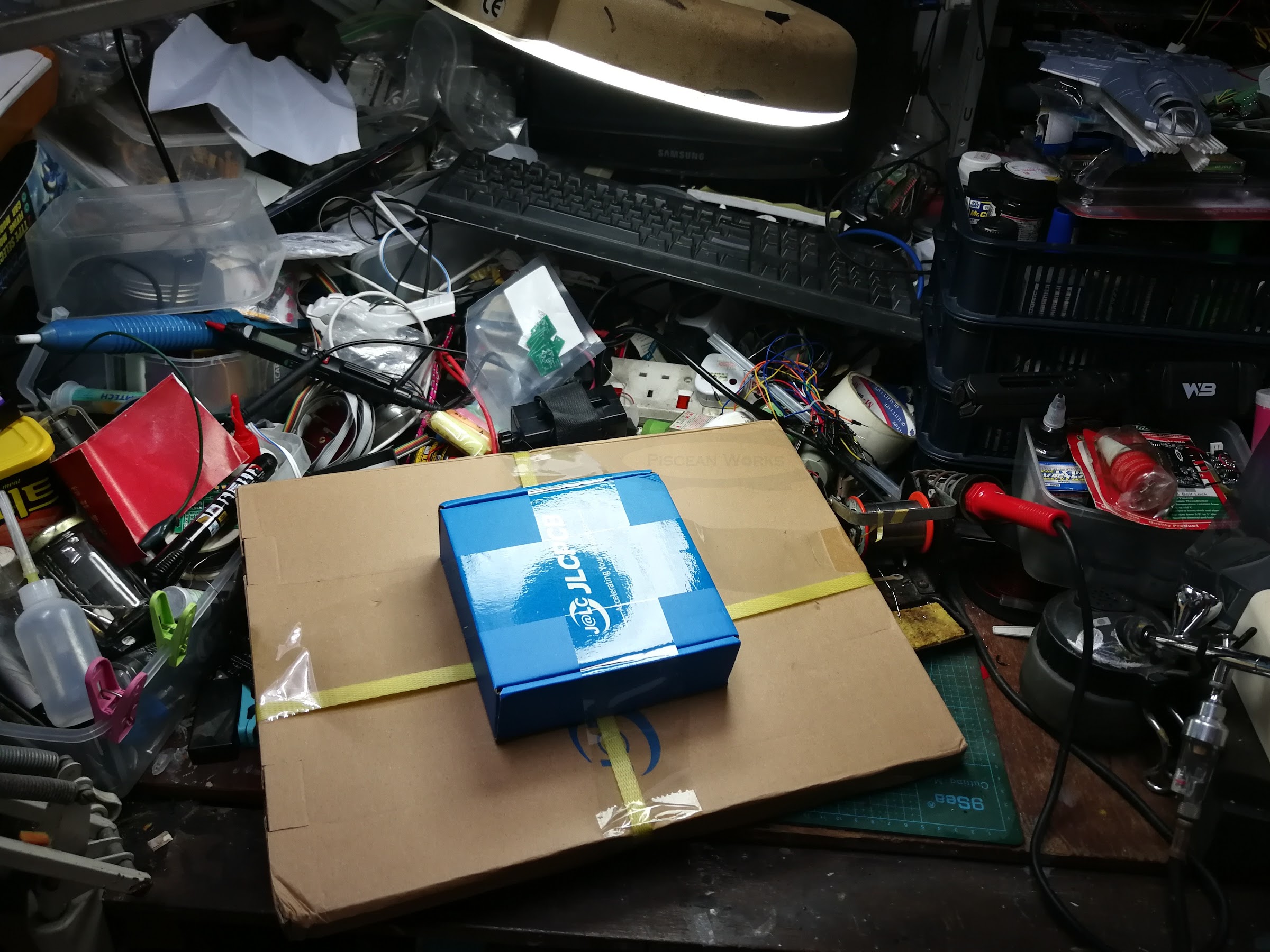
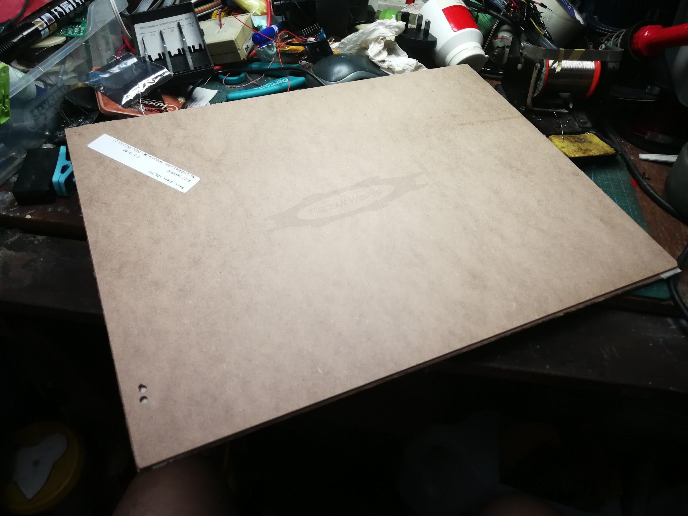
This came about more than a month ago from JLCPCB but I was too busy to open it. Not only that, looking for a working space big enough was also another issue. To be honest, I forgot about the huge size of the solder paste stencil, which measures close to an A3 sheet give to take. So, it was quite a challenge to reveal it on my Works table where space is a premium.
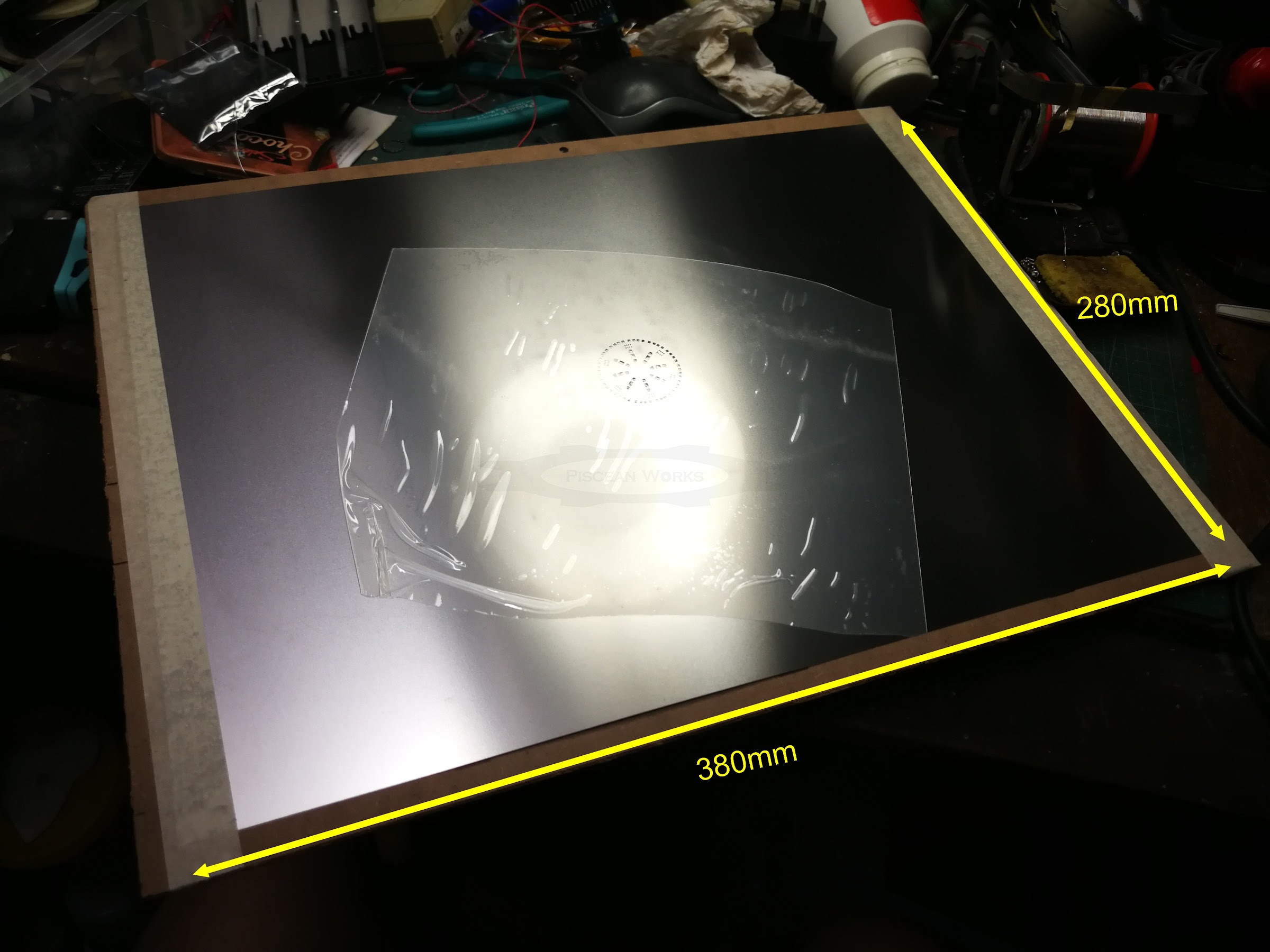
THE SOLDER PASTE STENCIL
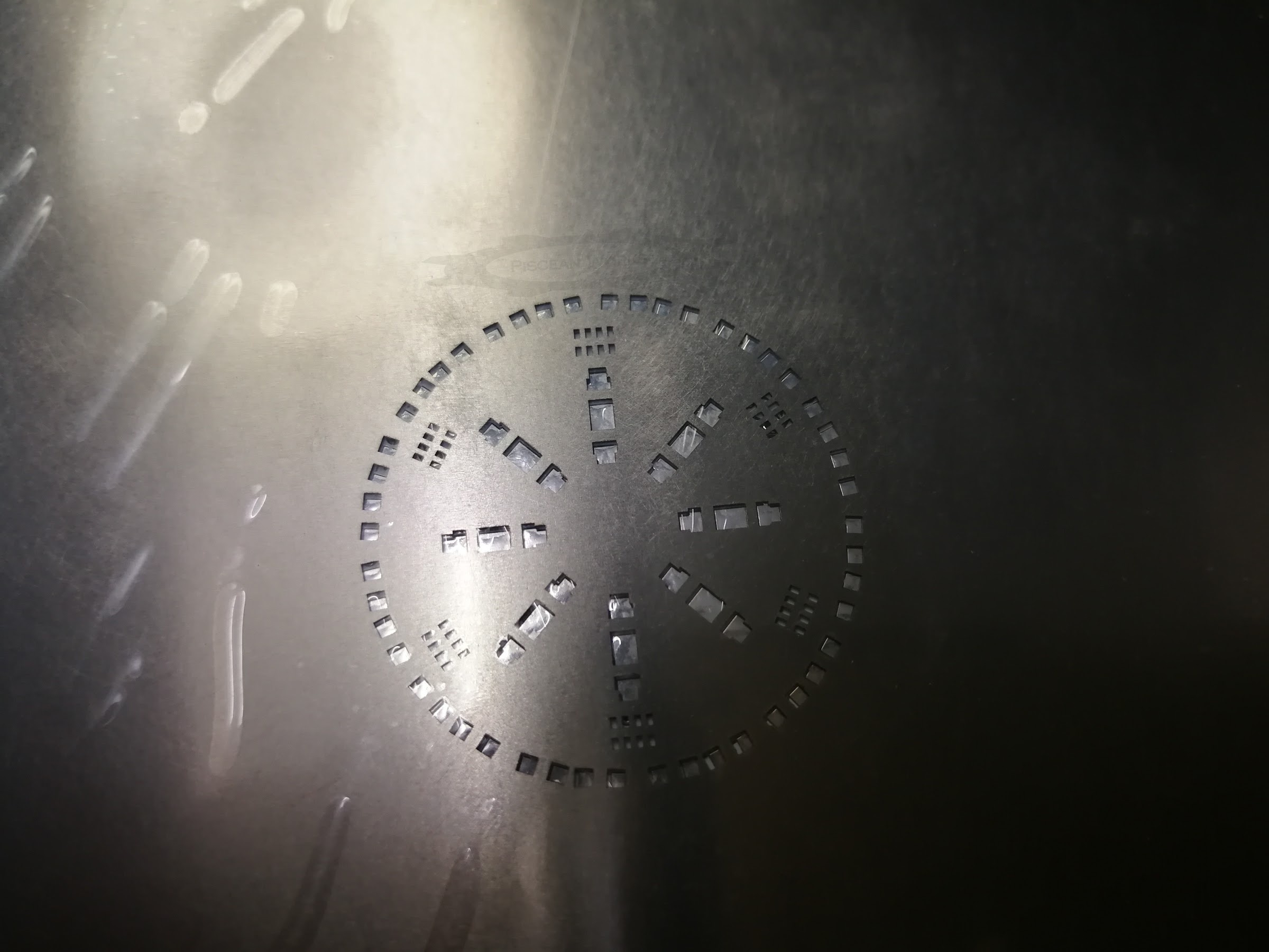
The solder paste stencil from JLCB PCB is a thin sheet of stainless steel metal. It has holes cut out so you can accurately apply the solder paste on the SMD solder pads on your PCB. Think of it as a form of silkscreen mask for colours. The stencil from JLCPCB is huge and it offers a usable area of 290mm x 190mm.
The next step is to create a jig to secure the PCB under the stencil so that the stencil aligns as accurately as possible with the PCB’s solder pads. This is a very simple step but unfortunately, my PCB design is round and not rectangular. When I have more time, I will need to look into this issue. Do watch the YouTube video below, courtesy of Electronoobs, who demonstrates how the stencil is to be used.
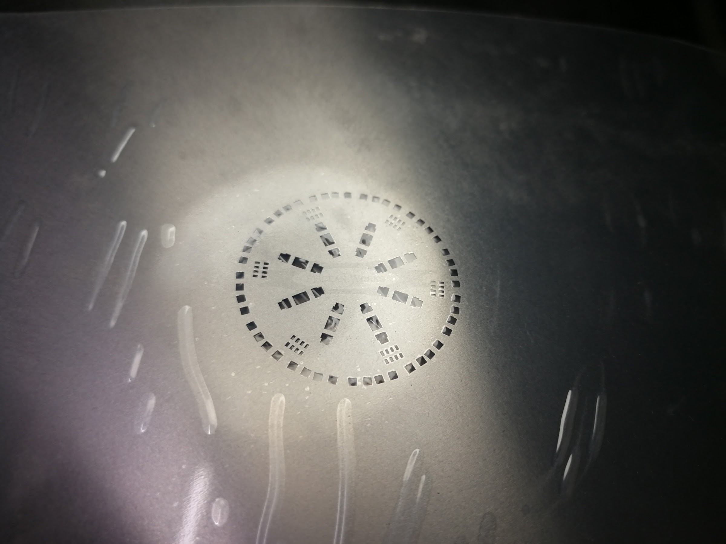
See those small little eight rectangles grouped together in two rows? There are 6 of them. These are for the SMD resistor arrays where it was so difficult to solder them reliably. I had to use plenty of solder flux and lots of checking to make sure those darn thing was soldered.

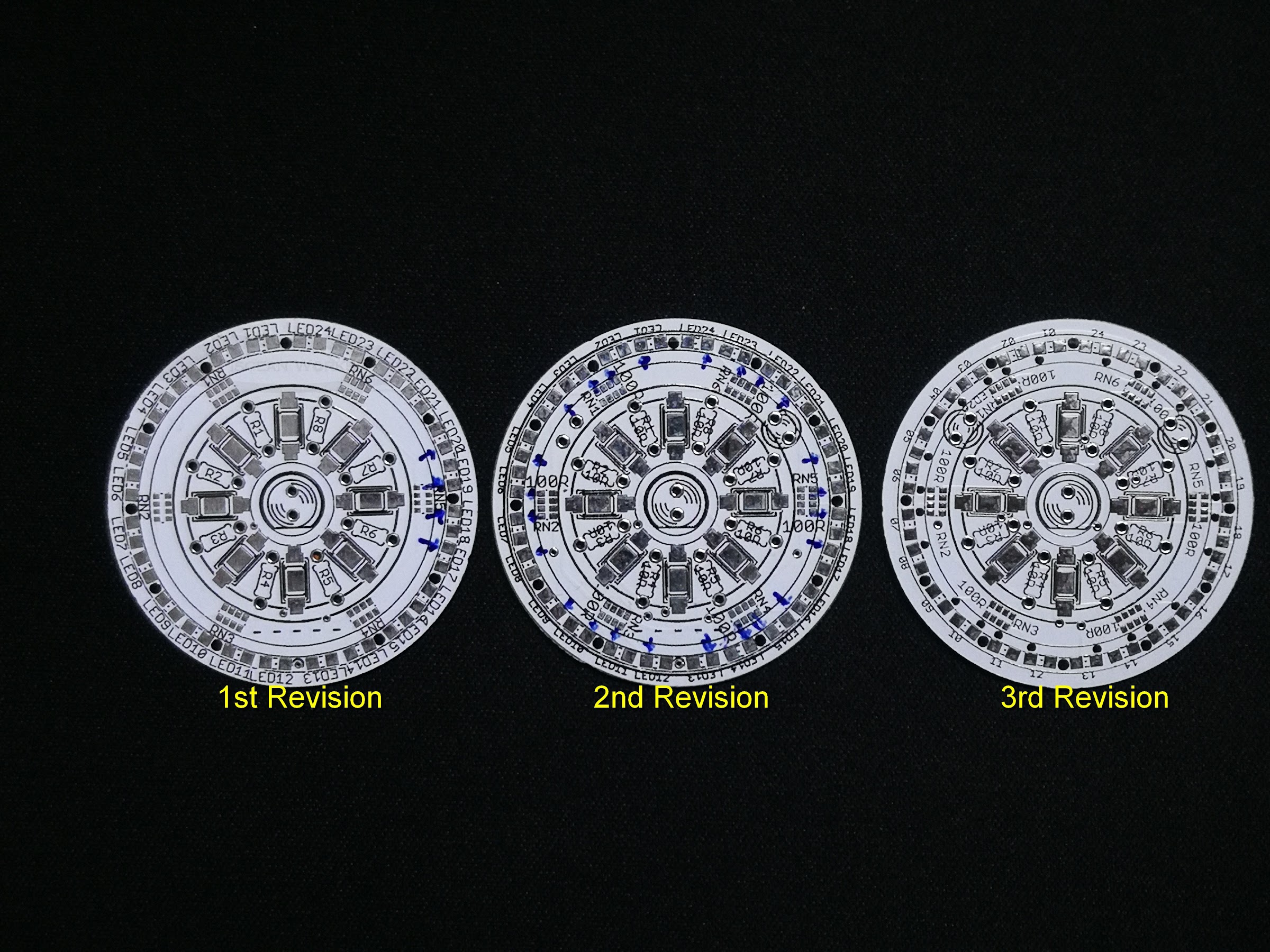
ENGINE PCB EVOLUTION
When the stencils arrived, so did the latest revision of the Razor Crest’s Engine PCB. I would have stopped with only two revisions but I had to modify the design to use the stencil.
1st Version
This was the very first version where the 5730 LEDs successfully lit up without any heating issue. It is connected via a 6-way ribbon cable.
2nd Version
The two red navigation LEDs were added in and the circuit was slightly modified to still use the 6-way ribbon cable. Once I realised that the Engine would not be ON when it has landed (ie Standby Mode), neither were the pair of red LEDs. This means that there are now only 6 wires treading inside the model from the Engines instead of 10.
3rd Version
The outer ring of 0603 LEDs were brought in closer to the centre by about 0.5mm. This is so that they do not get knocked/ destroyed by the plastic edges when inserting into the engines. It also has markings to identify the polarity of the 0603 SMD LEDs when populating the PCB after the stenciling stage.