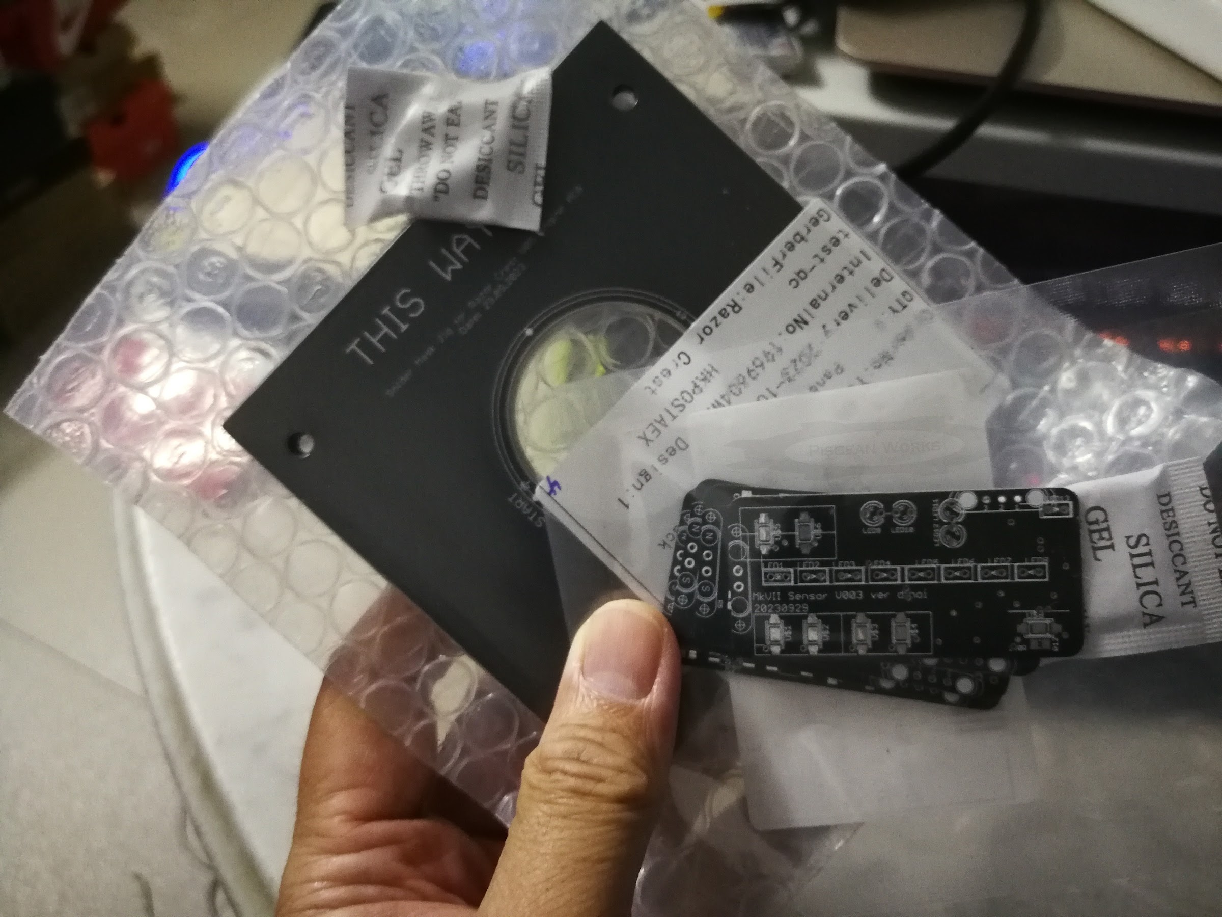
I got the template back just yesterday and to be frank, I was worried that it might not fit. If you watched YouTube videos, you’d see the Author arranging some PCBs surrounding the actual circuit board before using the solder mask template. This method ensures the template is height-matched as accurate as possible with the target PCB. When the the solder paste is applied, it would spread as accurate as possible, just like screen-printing a T-shirt. Alas, I could not follow suit because my PCB is round.
SO WHAT CAN I DO?
Placing other PCBs of the same thickness (1.1mm) might work. It would be a lot of work aligning the mask and all the PCBs. Plus, if the bottom wooden board flexes, the surrounding PCBs would follow too. There and then, I decided to make my own jig, with the help of JLCPCB, of course.
Basically, the idea is to just another PCB measuring 100mm x 100m square with a hole in the middle.
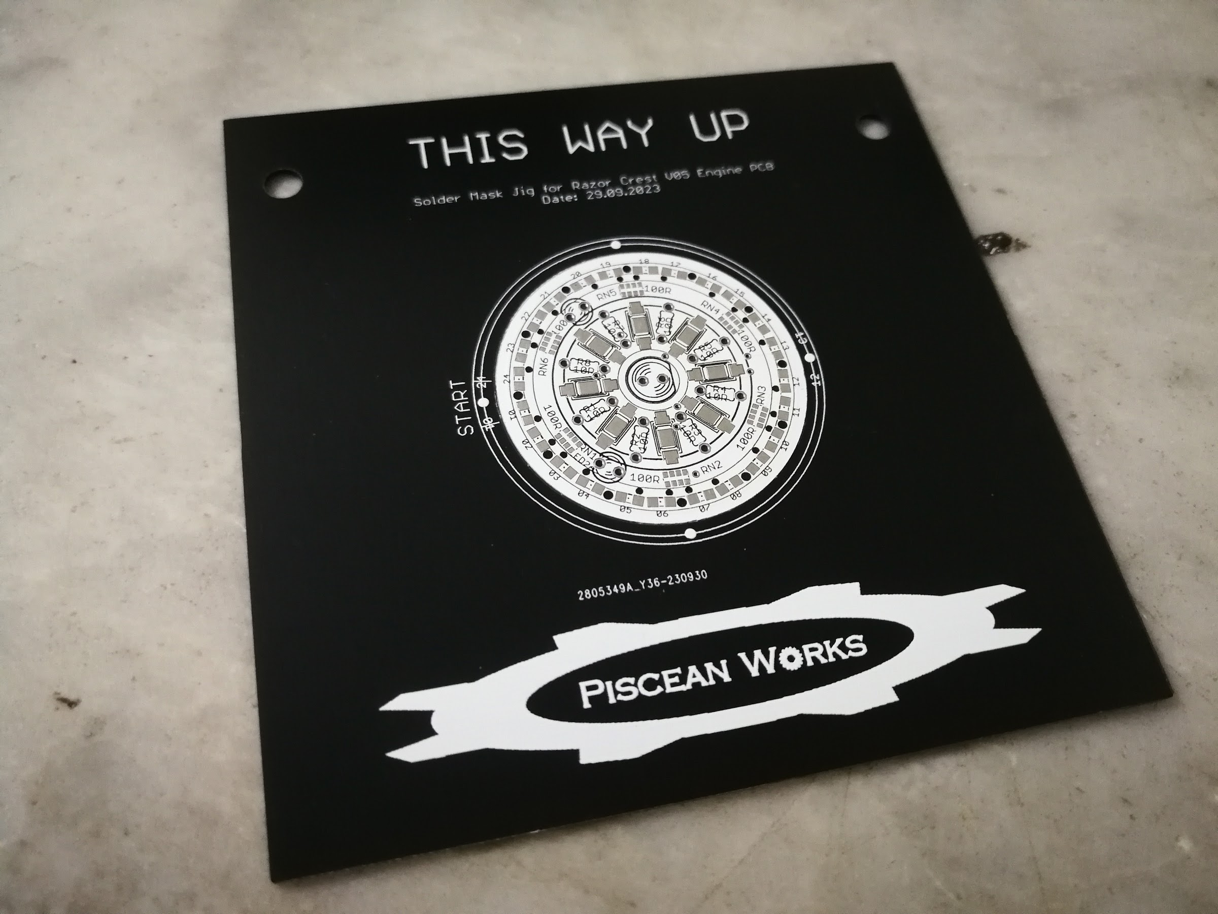
MY SQUARE DONUT (aka SOLDER MASK TEMPLATE)
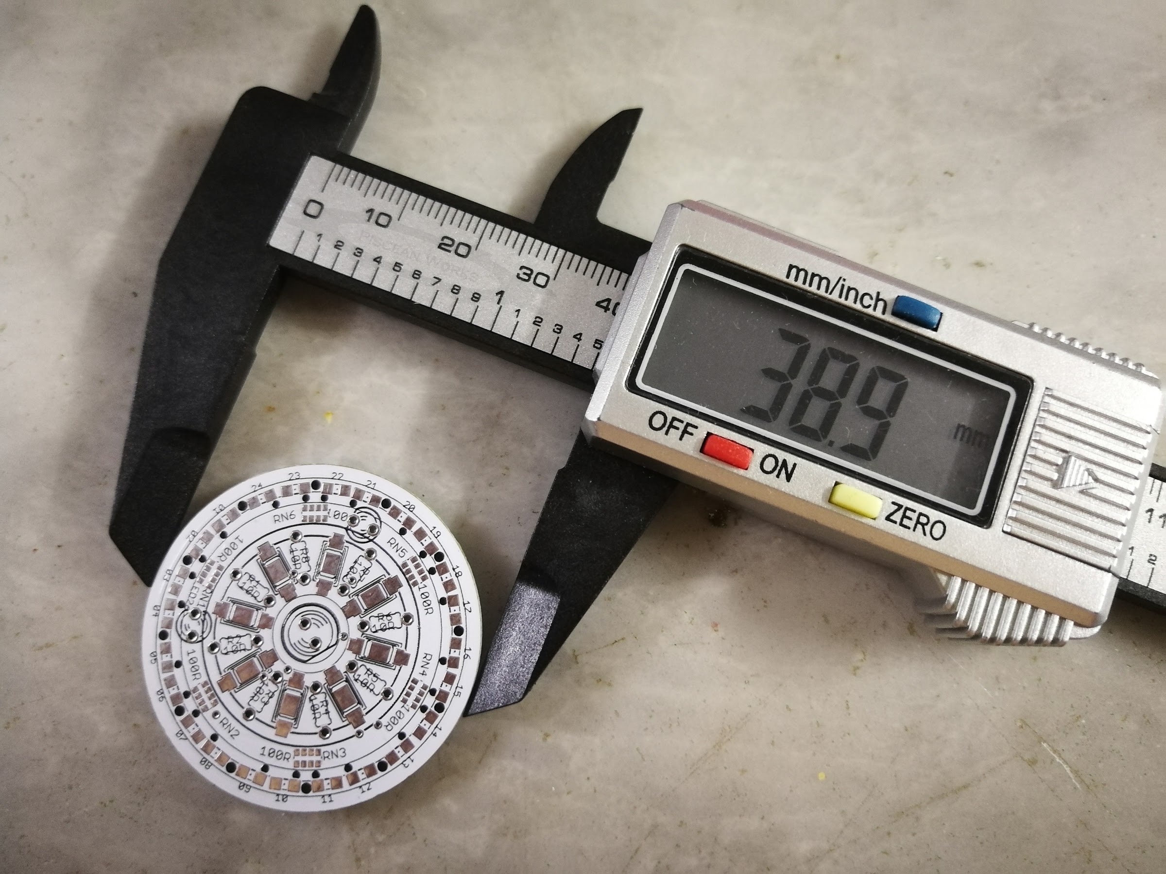
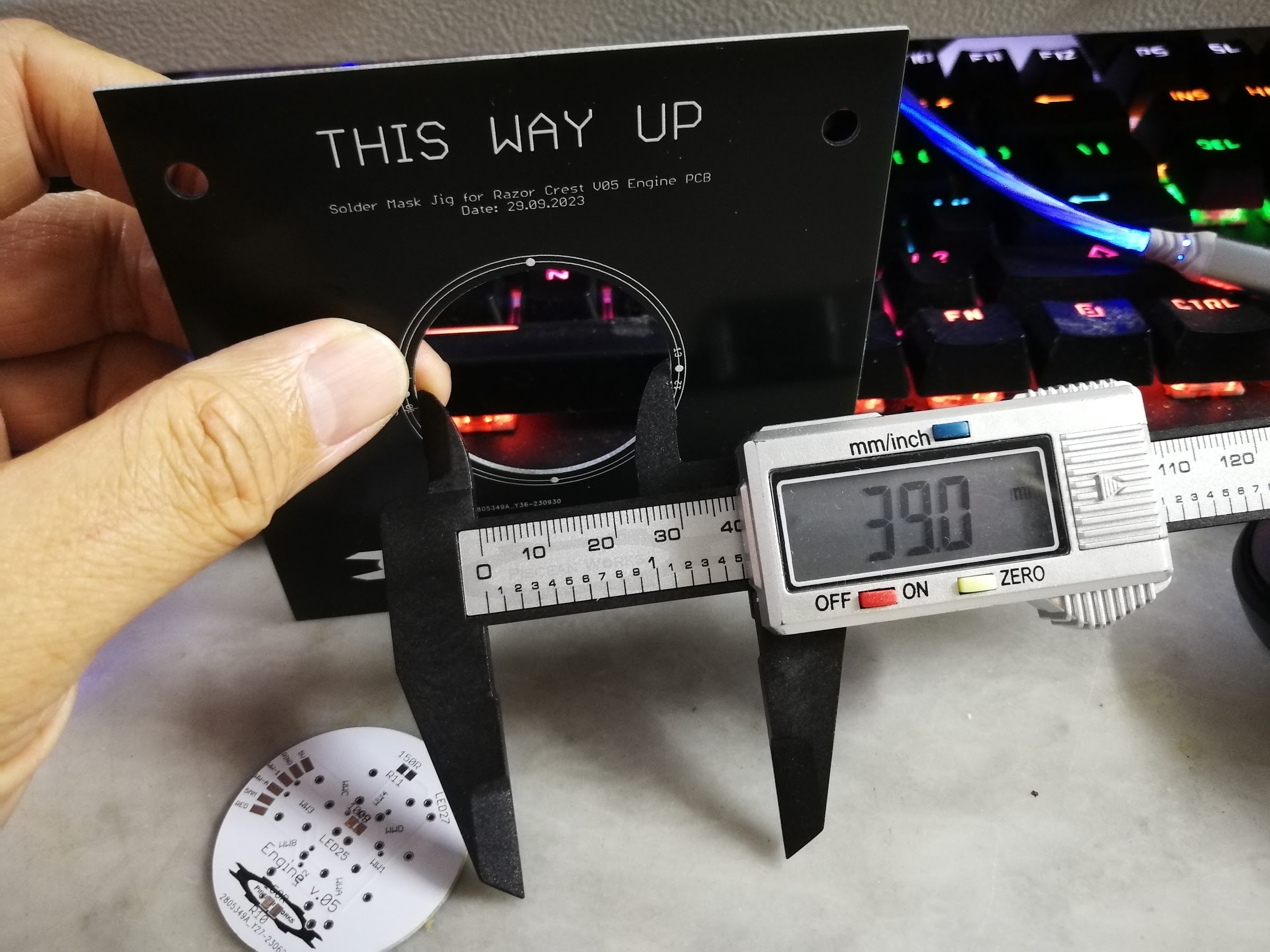
After overcoming my emotional uneasiness, I finally placed the Razor Crest Engine PCB onto the Donu, er, template and…
YES! It worked! Although there is a slight free-play but other than that, the fit is good. This was a very simple design but it still took me days to complete it. Plus, in trying to make up for lost time, I made a mistake. Initially, I wanted to store the template ( along with possible future templates) in an A4 ring binder, using the rings to keep the templates in place. So, yes, the measurement was off by about 10mm or so.
Not only that, I wanted to add on a small little key or triangle into the hole so that future PCBs will lock into the template without much alignment. Alas, the EaglePCB does not allow such possibility of joining a line to a circle (yet) and as much as I tried it even on the Fusion360, it did not work. There was a video on YouTube but it was all to no avail. Anyway, as backup, I added some alignment dots instead, with the word START.